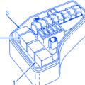
| Fuses | Usage | Ampere |
|---|---|---|
| 1 | Coolant Fan(Radiator) | 50A |
| 2 | Power Steering | 80A |
| 3 | Feed to Passenger Compartment Fuse Box | 60A |
| 4 | Feed to Passenger Compartment Fuse Box | 60A |
| 5 | Element, Climate Unit | 80A |
| 6 | Not In Use | |
| 7 | ABS Pump | 30A |
| 8 | ABS Valve | 20A |
| 9 | Engine Functions | 30A |
| 10 | Ventilation Fan | 40A |
| 11 | Headlight Washers | 20A |
| 12 | Feed to Heated Rear Window | 30A |
| 13 | Starter motor Relay | 30A |
| 14 | Trailer Connector (Accessory) | 40A |
| 15 | Not In Use | - |
| 16 | Feed to Audio System | 30A |
| 17 | Windshield Wipers | 30A |
| 18 | Feed to Passenger Compartment Fuse Box | 40A |
| 19 | Not In Use | - |
| 20 | Horn | 15A |
| 21 | Not In Use | |
| 22 | Not In Use | - |
| 23 | Engine/Transmission Control Module | 10A |
| 24 | Not In Use | |
| 25 | Not In Use | - |
| 26 | Ignition Switch | 15A |
| 27 | A/C Compressor | 10A |
| 28 | Not In Use | - |
| 29 | Front Fog Lights | 15A |
| 30 | Not In use | |
| 31 | Not In Use | - |
| 32 | Fuel Injectors | 10A |
| 33 | Heated Oxygen Sensor, Vacuum Pump | 20A |
| 34 | Ignition Coils, Climate Unit Pressure Sensor | 10A |
| 35 | Engine Sensor Valves, A/C Relay, Relay Coil, PTC Element Oil Trap, Canister, Mass Air meter | 15A |
| 36 | Engine Control Module, Throttle Sensor | 10A |
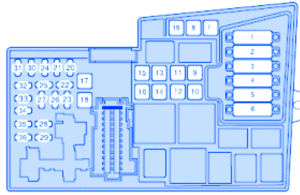
Volvo XC 2009 Main Engine Fuse Panel/Board – Fuse Symbol Map

