Suzuki Sidekick 2000 Pin Out Electrical Circuit Symbol Map
Tag Archive: suzuki sidekick
Apr 09
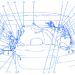
Suzuki Sidekick 2001 Front Engine Electrical Circuit Wiring Diagram
SYMBOLDESCRIPTION1Front Wiper Motor2Brake Fluid Level Switch3ABS Solenoid (Right)4ABS Solenoid (Left)5ABS Actuator6Brake Differential Switch7ABS Enable Relay8ABS Check Relay9Intake Air Temperature (IAT) Sensor10G611Front Speed Sensor (Left)12Power Steering Pump Pressure Switch13Mass Air Flow Sensor14Noise Filter (Suppressor)15Heated Oxygen Sensor No.116Cruise Control Actuator174 A/T Diagnosis Connector18Diagnosis Connector19Front Speed Sensor (Right)20DRL Resistor21Rear Washer Motor22G123Front Washer Motor24Tank Pressure Control Solenoid Valve25EVAP …
Sep 19
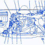
Suzuki Sidekick 1998 Front Engine Fuse Box/Block Circuit Breaker Diagram
SymbolDescriptionInformation Sensor1Mass Airflow Sensor2Not Used3Heated Oxygen Sensor4Power Steering Pressure Switch5Engine Coolant Temperature Sensor6Battery7Throttle Position Sensor8Shift Switch (A/T)9Cam Position Sensor (In Distributor)10Ignition Coil11Vehicle Speed SensorControlled DevicesaFuel Pump RelaybFuel InjectorcEGR Solenoid Vacuum ValvedEVAP Solenoid Purge ValveeIdle Speed Control (ISC) SolenoidfIgnitorgMalfunction Indicator Light (ML)hOxygen Sensor Heater RelayOtherAEngine Control Module (ECM)BMain RelayCFuse Block (Passenger Comp)EDLC Engine Monitor Connector …
Mar 29
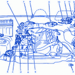
Suzuki Sidekick 1995 Main Engine Fuse Box/Block Circuit Breaker Diagram
SymbolDescriptionInformation Sensor1Mass Airflow Sensor2Not Used3Heated Oxygen Sensor4Power Steering Pressure Switch5Engine Coolant Temperature Sensor6Battery7Throttle Position Sensor8Shift Switch (A/T)9Cam Position Sensor (In Distributor)10Ignition Coil11Vehicle Speed SensorControlled DevicesaFuel Pump RelaybFuel InjectorcEGR Solenoid Vacuum ValvedEVAP Solenoid Purge ValveeIdle Speed Control (ISC) SolenoidfIgnitorgMalfunction Indicator Light (ML)hOxygen Sensor Heater RelayOtherAEngine Control Module (ECM)BMain RelayCFuse Block (Passenger Comp)EDLC Engine Monitor Connector …


