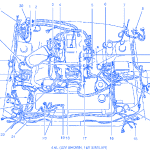
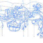
SYMBOLDESCRIPTION1EVAP Canister Purge Valve2A/C Clutch Cycling Pressure Switch3Throttle Position (TP) Sensor4Idle Air Control (IAC) Valve5Fuel Rail Pressurer Transducer6Brake Fluid Level Switch7Windshield Wiper Motor8C1059EGR Vacuum Regulator (EVR) Solenoid10Battery Junction Box11Brake Sensor (Left Front)12C10013C11314G10215Daytime Running Lamps (DRL) Module16Fuse Link A/B17Engine Oil Pressure Switch18Crankshaft Position (CKP) Sensor19Electric Cooling Fan Motor20Anti-Lock Brake Control Module21A/C High Pressure Cutout/Fan Switch22Engine …
Tag Archive: ford
Jun 20
Ford F350 2002 Data Link Connector Electrical Circuit Wiring Diagram
PinCircuitCircuit Function1-Not Used2914 (TN/OG)SCP Bus +3693 (OG)UBP Diagnostics457 (BK)Ground5670 (BK/WH)Ground6-Not Used770 (LB/WH)ISO Bus8-Not Used9-Not Used10915 (PK/LB)SCP Bus -11-Not Used12-Not Used13107 (VT)Module Programming Signal14-Not Used15-Not Used1640 (LB/WH)Voltage Supplied at All Times (Overload Protected) Ford F350 2002 Data Link Connector Electrical Circuit Symbol Map
Jun 13
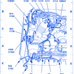
Ford Mustang GT 2001 Electrical Circuit Wiring Diagram
SYMBOLDESCRIPTIONA7ABS Control Module (2C219)A426Constan Control Relay Module (CCRM)B14Wheel Speed Sensor, Right Front (2C204)B22Mass Air Flow (MAF) Sensor (12B579)E7Headlamp, Right (13008)E42Fog Lamp, Right Front (15200)E166Park/Turn Lamp, Right Front (13411)M37Engine Cooling Fan MotorN412A/C Clutch Cycling Pressure Switch (19D594)P66Coil On Plug(COP)1(12029)P67Coil On Plug(COP)2(12029)P68Coil On Plug(COP)3(12029)P69Coil On Plug(COP)4(12029) Ford Mustang GT 2001 Electrical Circuit Symbol Map

