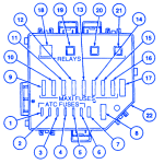
Cavity NumberRatingColorCircuit Protected125ANaturalPower Seats220AYellowHorn, Fog Lamps, Daytime Running Lamps. Control Module325ANaturalInterior Lamps425ANaturalAudio520AYellowAlternator630ALt. GreenCigar Lighter730ACircuit BreakerConvertible Top Motor860ALt. BlueAnti-Lock Brake System (ABS)940AAmberIgnition Switch1040AAmberIgnition Switch1140AAmberIgnition Switch1250ARedHeadlamps1320AYellowElectronic Engine Control1440AAmberHeated back Window1520AYellowFuel Pump1660ALt. BlueEngine Cooling Fan1730ALt. GreenThermactor Air Pump (4.6L4V Only)18–Not Used19Relay-Horn20Relay-Starter21Relay-Fog lamps22–Power Distribution Box Ford Mustang GT 1997 Power Distribution Fuse Panel/Board – Fuse Symbol Map
Tag Archive: ford mustang gt
Jun 21
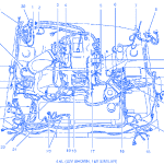
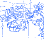
Ford Mustang GT 2000 Electrical Circuit Wiring Diagram
SYMBOLDESCRIPTION1EVAP Canister Purge Valve2A/C Clutch Cycling Pressure Switch3Throttle Position (TP) Sensor4Idle Air Control (IAC) Valve5Fuel Rail Pressurer Transducer6Brake Fluid Level Switch7Windshield Wiper Motor8C1059EGR Vacuum Regulator (EVR) Solenoid10Battery Junction Box11Brake Sensor (Left Front)12C10013C11314G10215Daytime Running Lamps (DRL) Module16Fuse Link A/B17Engine Oil Pressure Switch18Crankshaft Position (CKP) Sensor19Electric Cooling Fan Motor20Anti-Lock Brake Control Module21A/C High Pressure Cutout/Fan Switch22Engine …
Jun 13
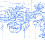
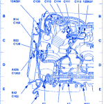
Ford Mustang GT 2001 Electrical Circuit Wiring Diagram
SYMBOLDESCRIPTIONA7ABS Control Module (2C219)A426Constan Control Relay Module (CCRM)B14Wheel Speed Sensor, Right Front (2C204)B22Mass Air Flow (MAF) Sensor (12B579)E7Headlamp, Right (13008)E42Fog Lamp, Right Front (15200)E166Park/Turn Lamp, Right Front (13411)M37Engine Cooling Fan MotorN412A/C Clutch Cycling Pressure Switch (19D594)P66Coil On Plug(COP)1(12029)P67Coil On Plug(COP)2(12029)P68Coil On Plug(COP)3(12029)P69Coil On Plug(COP)4(12029) Ford Mustang GT 2001 Electrical Circuit Symbol Map

