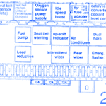
FUSE NO.AMPSCIRCUIT130ARadiator Fan210AStop Lights315ACigarette Lighter, Radio, Clock, Interior Lights, Central Locking System415AEmergency Flasher System515AElectric Fuel Pump6-Vacant710ATail, Parking and Side Marker Lights Left810ATail, Parking and Side Marker Lights Right910AHigh Beam Right, High Beam Indicator Light1010AHigh Beam Left1115AWindshield Wiper/Washer1215ARear Window Wiper/Washer, Coolant Level Checking Device, Outside Rear View Mirror Adjustment1315ARear Window Defogger, Heated Rear View Mirror1420AFresh …
Tag Archive: chevy
Jan 12
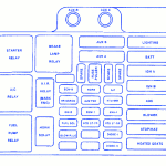
Chevy 3500 6.5 Manual 1998 Fuse Box/Block Circuit Breaker Diagram
Fuse/Relay Map-Starter Relay-A/C Relay-Fuel Pump Relay-Brake Lamp Relay-AIR Relay-Horn Relay-AUX B-AUX A-Fuse Puller-ECM-B-RR DEFOG-IGN-E-FUEL SOL-GLOW PLUG-HORN-AUX FAN-ECM-1-HTD ST-FR-A/C-HTD MIR-ENG-1-HTD ST-RR-DIODE-1-DIODE-2-LIGHTING-BATT-IGN A-IGN B-ABS-BLOWER-STOP/HAZ-HEATED SEATS Chevy 3500 6.5 Manual 1998 Fuse Panel/Board – Fuse Symbol Map
Dec 05
Chevy Tracker 2003 Dash Fuse Box/Block Circuit Breaker Diagram
SYMBOLDESCRIPTIONP/WPower WindowsDOMDome LightTAILLicense Plate Light, Clearance/Marker Lights, Instrument Panel IlluminationHAZHazard LightsIGO2 Sensor Heater, Cruise Control, Ignition Coil, Meter, G SensorCIGCigar/Cigarette Lighter, Radio, Power MirrorD/LDoor LocksSTPBrake Light, Horn, Centre High-Mounted Stop LampFOGNot UsedDEFRear Window Defogger, DRLS/HNot UsedTRNTurn Signal, Back-Up LightWIPWindshield Wiper/Washer, Rear Window Wiper/Washer Chevy Tracker 2003 Dash Fuse Panel/Board – Fuse Symbol Map
Dec 02
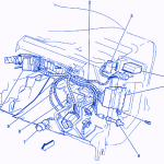
Chevy Blazer 1994 Inside Dash Electrical Circuit Wiring Diagram
SymbolDescription1Not Used2Splice S2013Panel Dimmer Switch4Headlamp Switch5I/P Fuse Block6Front Side Door Jamb Switch,LH7Consiole Courtesy Lamp, LF8Instrument Cluster9Splice S21010Daytime Running Lamps Control Module and I/P Wiring Diode Module Chevy Blazer 1994 Inside Dash Electrical Circuit Symbol Map
Nov 23
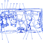
Chevy Metro L-4 2001 Junction Box Electrical Circuit Wiring Diagram
SYMBOLDESCRIPTION1Suplemental Inflatable Restraint (SIR) Harness2Duty Check Data Link Connector3Inflatable Restraint IP Module Connector4Engine Wiring Harness5Powertrain Control Module (PCM) C16Powertrain Control Module (PCM) C27Powertrain Control Module (PCM) C38Junction Block9Turn Signal/Combination Switch Connector10Floor Harness11Power Door Lock Control Module12Main Wiring Harness13Electronic Brake Control Module (EBCM) C1 With ABS14Electronic Brake Control Module (EBCM) With ABS15Electronic Brake Control Module …


