| FUSE | FUNCTION |
|---|---|
| 1 | Air Conditioner Clutch |
| 2 | Electronic Throttle Control |
| 3 | Engine Control Module (IGN 1)(LZ4,LZ9) |
| 4 | Transaxle Control Module Ignition 1 |
| 5 | Mass Airflow Sensor (LY7) |
| 6 | Emission |
| 7 | Left Headlamp Low Beam |
| 8 | Horn |
| 9 | Right Headlamp Low Beam |
| 10 | Front Fog Lamps |
| 11 | Left Headlamp High Beam |
| 12 | Right Headlamp High Beam |
| 13 | Engine Control Module (BATT)(LE5,,LY7) |
| 14 | Windshield Wiper |
| 15 | Anti-Lock Brake System (IGN 1) |
| 16 | Engine Control Module (IGN 1)(LE5, LY7) |
| 17 | Cooling Fan 1 |
| 18 | Cooling Fan 2 |
| 19 | Run Relay, Heating , Ventilation, Air Conditioning Blower |
| 20 | Body Control Module 1 |
| 21 | Body Control Module Run/Crank |
| 22 | Rear Electrical Center 1 |
| 23 | Rear Electrical Center 2 |
| 24 | Anti-Lock Brake System |
| 25 | Body Control Module 2 |
| 26 | Starter |
| 41 | Electric Power Steering |
| 42 | Transaxle Control Module Battery |
| 43 | Ignition Module (LE5, LZ4, LZ9) Odd Cylinder Injectors/Ignition Coils (LY7) |
| 44 | Injectors (LE5, LZ4, LZ9), Even Cylinder Injectors/Ignition Coils (LY7) |
| 45 | Rear Oxygen Sensors |
| 46 | Daytime Running Lamps |
| 47 | Center High-Mounted Stoplamp |
| 50 | Front Power Windows Coupe/Retractable Hardtop |
| 51 | Engine Control Module (BATT)(LZ4, LZ9) |
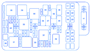
Pontiac G6 2007 Engine Compartment Fuse Panel/Board – Fuse Symbol Map


