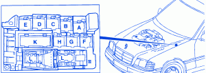
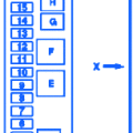
| Relay Code | Abbreviation | Designation |
|---|---|---|
| A | K35 | O2S 2 (After TWC) Heater Relay Module |
| B | K20 | ASR Charging Pump Relay Module (Up To 11/94) |
| K17 | AIR Relay Module | |
| C+D | K9 | Auxiliary Fan Relay Module (Stage 1[up to 11/94]and 2) |
| K9K1 | Auxiliary Fan Relay (Stage 1)(Up To 11/94) | |
| K9K2 | Auxiliary Fan Relay (Stage 2)(Up To 11/94) | |
| C | K9/1 | Auxiliary Fan Relay Module (Stage 1)(11/94-08/95)- Reserve (as of 09/95) |
| D | K10 | Auxiliary Fan Relay Module (Stage 2)(11/94-08/95)- Reserve (as of 09/95) |
| E | K2 | HCS Relay Module |
| F | K39 | Horn Relay Module |
| G | K19/1 | Separation Relay Module (Terminal 56/56b, Daytime Running Lamps)(Canada) |
| H | K20/1 | High-Pressure/Return Pump Relay (as of 06/94) |
| K | N10 | Combination Relay (Turn/Hazard Signal, Heater Rear Window, Wiper Motor) |
| L | N7 | Exterior Lamp Failure Monitoring Module |
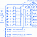
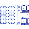
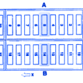
Mercy C280 1997 Main Engine Fuse Panel/Board – Fuse Symbol Map

