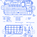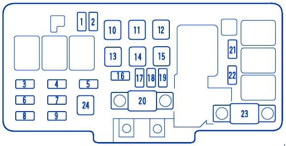
| No. | A | Circuit Protected |
|---|---|---|
| 1 | 20 | Spare Fuse |
| 2 | 30 | Spare Fuse |
| 3 | 15 | Right Headlight |
| 4 | 15 | ACGS |
| 5 | 15 | Hazard |
| 6 | – | Not Used |
| 7 | 20 | Stop |
| 8 | 15 | Left Headlight |
| 9 | 20 | ABS F/S |
| 10 | 40 | Power Window Motor |
| 11 | 30 | Power Sliding Door (EX and EX-L models) |
| 12 | 30 | Rear Defroster |
| 13 | 40 | Back Up, ACC |
| 14 | 40 | Power Seat (EX and EX-L models) |
| 15 | 40 | Heater Motor |
| 16 | 30 | Cooling Fan |
| 17 | 7.5 | Spare Fuse |
| 18 | 10 | Spare Fuse |
| 19 | 15 | Spare Fuse |
| 20 | 120 | Battery |
| 21 | 30 | Condenser Fan |
| 22 | 7.5 | MG Clutch |
| 23 | 50 | Ignition Switch (IG 1 Main) |
| 24 | 30 | ABS Motor |
Honda Odyssey RA6 1999 Engine Compartment Fuse Panel / Board – Fuse Symbol Map

