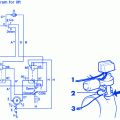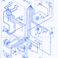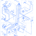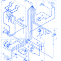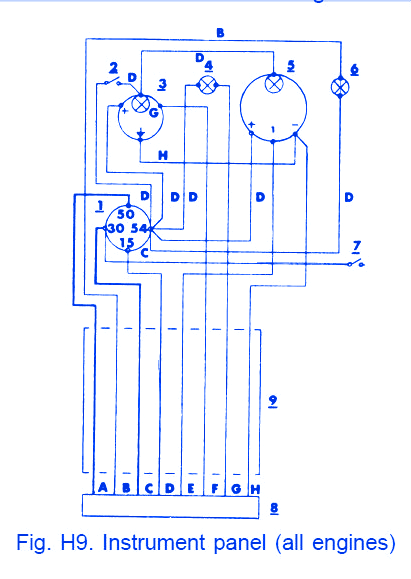
| SYMBOL | DESCRIPTION |
|---|---|
| Legend for Fig. H7,H8 and H9 | |
| 1 | Key Switch Witch Starter Contact |
| 2 | Instrument Lighting Switch |
| 3 | Temperature Gauge |
| 4 | Warning Lamp for "Low Oil Pressure" |
| 5 | Revolution Counter |
| 6 | Charging Control Lamp |
| 7 | Extra Switch |
| 8 | Connection Terminal |
| 9 | Cable Harness |
| 10 | Battery |
| 11 | Master Switch |
| 12 | Sterter Motor |
| 13 | Charging Regulator |
| 14 | Alternator (or D.C Generator) |
| 15 | Fuse |
| 16 | Oil Pressure Sender |
| 17 | Temperature Sender |
| 18 | Advance Engaging Resistor |
| 19 | Ignition Coil |
| 20 | Distributor |
| 21 | Connector |
| 22 | Cable Harness |
Bayliner Liberty 2250 1977 Instrument Panel Electrical Circuit Symbol Map

