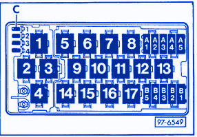
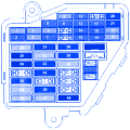
| SYMBOL | RELAY LOCATION |
|---|---|
| 1 | Open |
| 2 | Coolant FC(Fan Control) Relay, J135 |
| 3 | Third Speed Coolant FC(Fan Control) Relay, J135 |
| 4 | Fog Light Relay,J5 |
| 5 | Open |
| 6 | Intensive Washer Pump Relay, J75 |
| 7 | Daytime Running Light Relay (Switch-On), J90 (Canada Only) |
| 8 | Selector Level Light Relay, J307 |
| 9 | A/C Clutch Relay, J44 |
| 10 | A/C Clutch Control Module, J153 |
| 11 | Rear Window / Wiper Washer Relay, J31 |
| 12 | Open |
| 13 | Speaker Power Supply Relay, J225 |
| 14 | Lamp Control Module, Rear, J224 |
| 15 | Lamp Control Module, Rear, J224 |
| 16 | Control Module Alarm Horn, J31 |
| 17 | A/C Relay, J32 |
| CIRCUIT BREAKERS | |
| A1 | Automatic Window Closing Circuit Breaker (S99) |
| A2 | Central Looking System Motor Circuit Breaker (S85) |
| A3 | Power Window Circuit Breaker (S43) |
| A4 | Radio Circuit Breaker (S84) |
| A5 | Heated Seat Circuit Breaker (S79) |
| B1 | Memory Seat Adjusting Circuit Breaker (S44) |
| B2 | Power Seat Circuit Breaker (S80) |
| B3 | Door Lock Heating Element Circuit Breaker (S86) |
| B4 | open |
| B5 | Sunroof Circuit Breaker (S83) |
| DLC (Data Link Connector) | |
| C1 | (Black) B+ (Battery Positive Voltage) and Ground (GND) |
| C2 | (White) Rapid Data Transfer |
| C3 | (Blue) Blink Code Output |
| Diagnostic Connector Terminal | |
| K | DLC (Data Link Connector), Rapid Data Transfer |
| L | DLC (Data Link Connector), ECM (Engine Control Module) |
Audi Canada UrS6 1996 Main Fuse Panel/Board – Fuse Symbol Map

